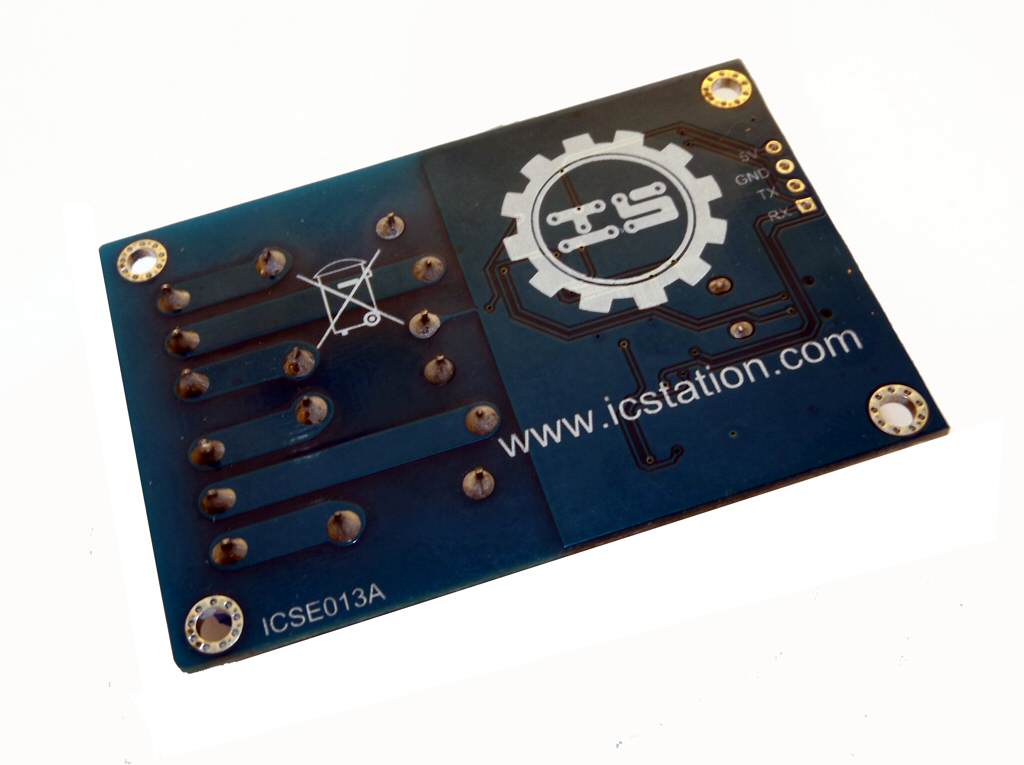
I don't know if the device is actually still produced, but it's part of a family of similar boards, along the ICSE012A (4 relays) and ICSE014A (8 relays). Here is the bare-bones board, it's shipped in bubble wrapped plastic bag with no instructions:
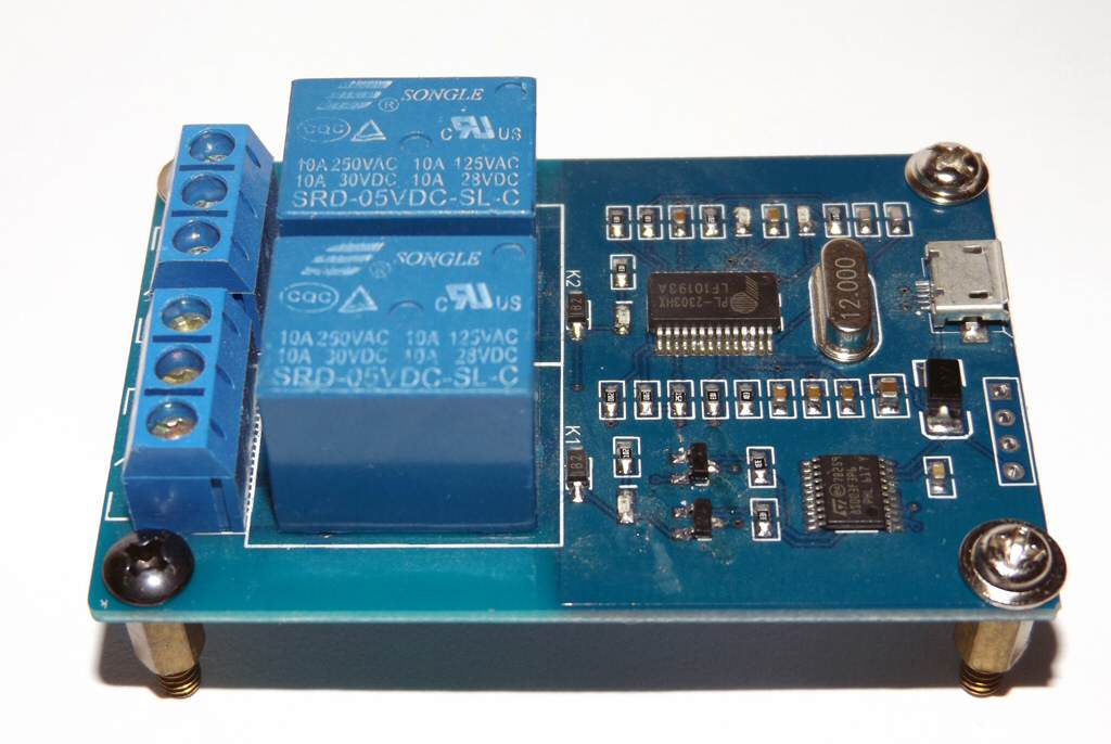
Now, regarding the 'Prolific' USB-Serial chip. I was aware of the problem before ordering the board, but it's really a counterfeit Prolific chip. These fake chips were very common in cheap USB-RS232 cables, until Prolific released drivers that recognized them and disabled the device in Windows, yellow icon and a Code 10 error. Counterfeit or not, these chips do work, but the lack of drivers, as well as the fastidious habit of the recent iteration of M$ operation systems to use only the most recent drivers from Windows Update render often these devices unusable. With other OSes like Linux there is no problem since the drivers have not this 'feature': it is however always possible to force an older still compatible driver with no particular issues. On Windows 7 64 bit I use the barebones zipped driver you can find here with an explanation. There is also this little program which could work better on Windows 8.x and 10 (but try the zipped driver first). In general google 'fake prolific chip fix' to get further informations and other drivers. With one of these fixes, the board will work in Windows. As far as I know, the other two boards with 4 and 8 relays all have fake chips.
From device manager it's seen in fact as Prolific USB-to-Serial Comm Port, and it's shown under the COM/LPT Tree. As with any other serial port, it's possible to assign a different COM port number from the properties dialog window.
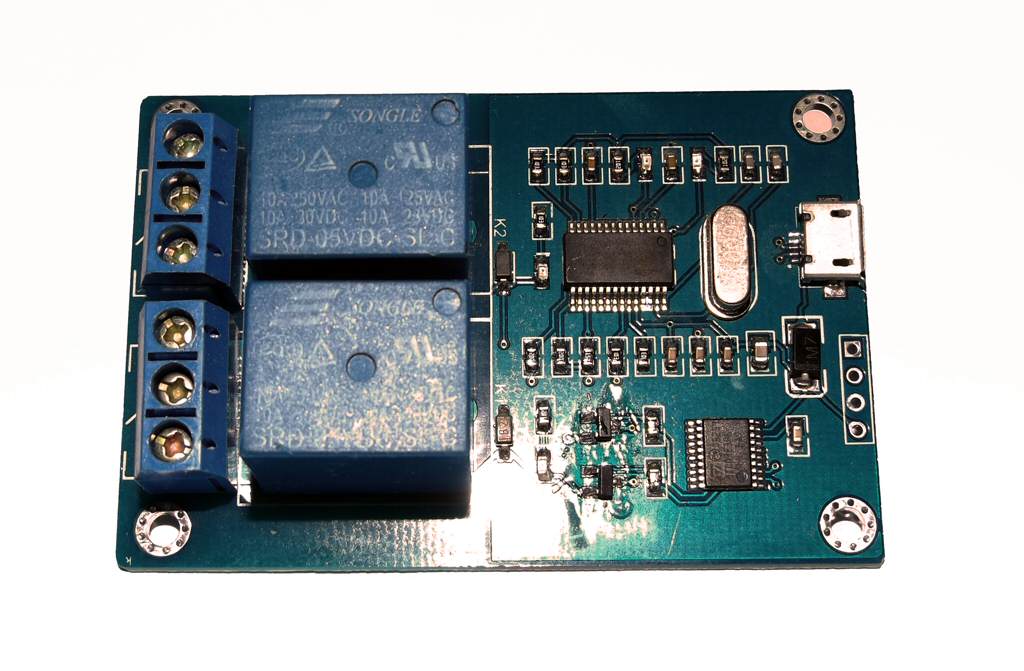
Unlike boards with more relays this particular one has no need of additional power other than the standard USB 500mA - it's probably better to use a board USB socket anyway. There are also four miniature LEDs, one for each relay and two to signal RX/TX. Strangely, the first relay LED is noticeably brighter in my case.
Software and documentation must be downloaded from the manufacturer's site. Try here - it's the 4 relay board, but it's the same. What you get is a test program for Windows and two pages of documentation. There is a chinese version and an almost incomprehensible 'chinenglish' translated version. The theory of operation is actually pretty simple, even if to verify it I resorted to monitoring the serial traffic from/to the test program with a serial software monitor. To control this board, and the others, one must operate as following :
- Set the serial parameters to 9600 bit/s, 8 bit data, no parity, 1 stop bit
- The board expects single byte commands and outputs single byte id packets.
- When plugged in/switched on the board expecs an hex 50 command. When sent this command before operations the board will respond with a single byte id code. For the ICSE013A 2 relay board its hex AD. AB for the 4 relay model and AC for the 8 relay model
- After this one must send an hex 51 command to start switching relays on and off. After this command, sending a request id hex 50 will no more result in the board sending back its id until it's switched off and then on.
- So to initialize the board first send hex 50, handle the id code if needed, then send hex 51.
- To switch relays on and off and on one must always compute a single byte command representing the status of the individual relays. The first relay is represented by the lowest order bit in the command byte, the second in the second lowest order bit, and so on for the other relays of the other boards. Of course a 'switched on' relay with the NO contact closed it's represented by a 1 bit, the reverse by a 0 bit.
- For the 2 relay board, the command to set both relays off it's 0, binary 00000000. To switch the second relay on, it's decimal 2, binary 00000010. To switch on both relays, it's dec 3, binary 00000011, to switch on the first relay, dec 1, binary 00000001.
- It must be noted that the command always switches on AND OFF relays according to its data. For example if both relays are on and I send a 00000001 command only the first relay will be kept on, since the second-lowest order bit it's 0, that is, switch off relay 2!
- In other words, the board does not keep the state of its relays in its protocol, this is always the programmer's responsibility. There are NO commands to retrieve the relays status.
- It's also important to set a starting state for the relays beginning operations, since the hex 51/50 commands act strangely in this respect (a 51 command seem to switch a relay off when issued for the second time, e.g.)
- Bits for relay not physically present on the board, for example trying to set the 8th relay on the 2 relay board, are simply ignored.
Now, after just a few hours of testing, the board started behaving erratically. Sometimes it shows 'Unknown USB device' when plugged in (on several hosts) - sometimes it works but only for a litte while. I suspect that one of the SMD capacitors or resistors on the board has experienced some infancy problem, or the Prolific chip is not only a fake, but also a trickster :-). The other relatively bigger M7 black component is a diode and it tests ok with my multimeter. Still good for the price and its purpose in my case, playing around. Using the other serial interface on the other hand does not show any problem: I soldered a 4 pin strip on the holes and I used an Arduino Uno as a testbed. The wiring is 5V board to 5V Arduino, GND board to GND Arduino, RX board to TX Arduino and TX board to RX arduino (TX/RX arduino are the first two digital pins). I wrote a simple sketch to loop the four possible relay states after initialising the board. It's on github too, here. It will work with other Arduino models and other Arduino serial with minimal modifications. RX/TX must always be connected 'crossing', and always remember that it's NOT an RS-232 level interface. The 5V lead will power the board, no need to connect to USB.
What can I say? For 2.75 EUR, it's OK; if it dies completely I'll scrounge the relays and the terminal blocks..
Have seen some relay boards with serial interface which can do daisy chain. Do you know if this is possible with this boardb
ReplyDeleteI don't think so, there's nothing in the documentation, not to mention the board itself
ReplyDelete