Sunday 27 August 2017

An ATX breakout board and how I modded it.


After a long hiatus I recently got interested again in electronics, an I'm in the process of setting up a minimal lab again. In order to get an additional bench power supply I considered converting an ATX PSU to a 'benchtop' power supply. ATX PSUs supply 5V,12V,-12V and 3.3V with more than sufficient amperage. They do not offer variable voltage nor they are current regulated, but the nominal outputs are stable and a lot of people - myself included - already have one or two ATX power supplies lying around.

At first, I considered modding directly my candidate PSU (a 500W Cooler Master unit, almost brand new). There are many tutorials about the procedure on youtube and other sites. For example, this video on the very interesting GreatScott! YT channel could be used as a starting point. There are many variations of this mod: some tutorials recommend dangerous practices, some projects do not make much sense (a Chinese bench PSU can be bough for under 50 EUR, it doesn't make a lot of sense to spend 20-30 EUR to mod an ATX with voltmeters, amperometers etc then) practically. The GreatScott! video is a minimal mod requiring very little additional components.

In the end I decided againts the procedure, the main reason being the fact that I'd like a fully reversible mod: I would like to be able to use the ATX PSU for testing motherboards from time to time, cutting the ATX connector and drilling holes goes a little bit against that.

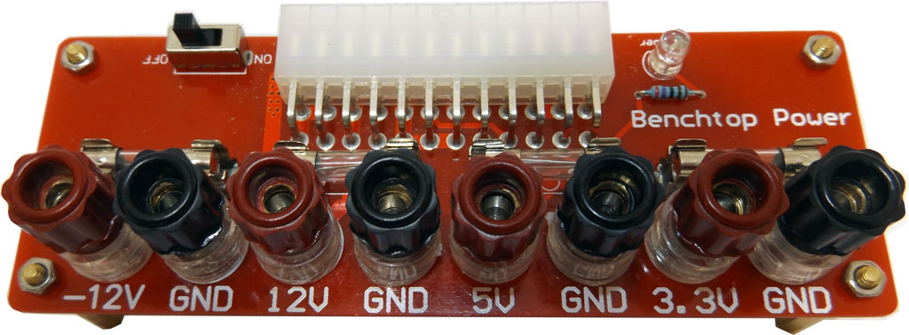
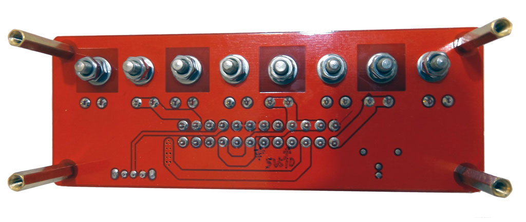
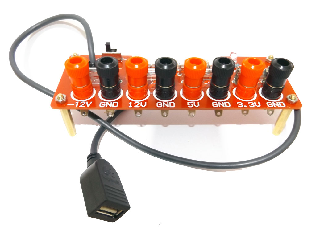
Enter the 'ATX breakout board'. A small circuit with an ATX female connector, a switch and some binding posts. The minimum required to turn on the PSU and use the four voltages in a circuit. I believe that the idea arose first in the open source hardware community. Anyway, nowadays one can buy a ready made circuit for less than 10 EUR. Just look for ATX breakout board on ebay or Amazon. First of all, let me say that the best available design overall it's not available ready made, but only in PCB form and/or in CAD files. It has been designed by an Italian, Francesco Truzzi and is described here. The board has everything, USB ports with recharging protocol support, variable voltage support, dummy load support, the works. Too much hassle though, so I decide to buy this model on Amazon.  It sports long brass distancers and a separate ground binding post for every voltage, as well as the lowest price, over other designs, like the 'Seedstudio' board. Here's my untouched board:

There's a small switch for the POWER ON ATX line and a blue power led. Of course, ATX PSUs are always 'on' as long they're plugged on mains and the switch on the back near the three prong socket is on. The switch merely connects a specific line to a 5V 'standby' rail which is always available, usually with a couple ampere  supply, turning on the rest of the PSU. One needs only to connect the ATX male connector to the female connector on board and switch everything on. This model works both with 20 pin and 24 pin ATX connector, the rails are connected correctly and I've tested them.
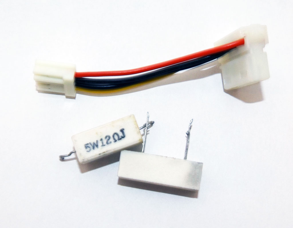
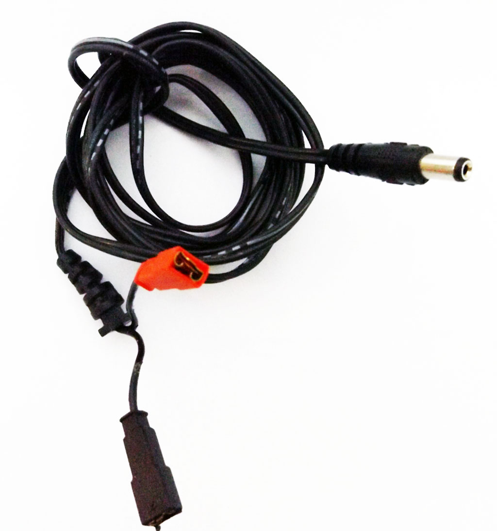
In comparison with other breakout boards this model lacks a dummy load resistor. Many ATX PSUs in fact do refuse to start if no load is connected to them. Usually a 10W 10 Ohm resistor connected to the +5V or the +12V rail will solve the problem. The best thing would be to load both rails. 10W power resistors are really the mininum for this kind of job. Other boards are usually shipped with a 10W white resistor to solder on specific holes already drilled on the PCB. On the other hand more recent PSUs start without a load with no problems. My unit does so, and there are no differences in measured voltages on the outputs with or without a load. I had planned to build a completely reversible, detachable dummy load recycling a 15 year old molex to floppy power cable and some scrounged power resistors:

but for the moment, I've no need. Really, do use 10W resistors, I've tried the 5W 12Ohm part shown, and it gets hot damn quick.

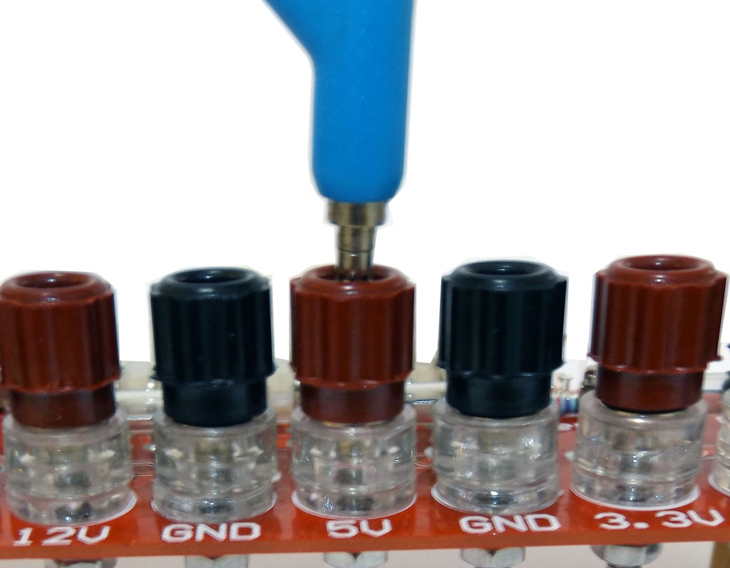
Back to our breakout board. One big problem is the binding posts. They do look like standard 4mm banana sockets, but 1) they are too short for a real banana plug 2) they don't even  have holes to put wires into:

They're usable, but what the heck, I decided to change them with standard, longer posts you can find anywhere. I'll find a use for the original posts sometime. They're  secured with a couple of nuts, not soldered. One modification I could really find usable is to add a USB port for chargin/powering things up. The ideal solution is the one designed by Francesco Truzzi: add the USB connectors on the board, with support for USB negotiation and charging protocols via the TPS2513 chip. But a simple usb cable connected directly to the 5V rail with no additional components will work. I used one of the many USB extension cord I had lying around and cut it this way:

One need only to expose the GND (black) and +5V (red wires) . Now, one could safely connect them to the main 5V rail, with clip-on connectors even, but rememeber the 5V standby power with 2-3A I mentioned before. That line is always available, ideal for charging stuff!. The rail is not available on the posts of course, but is on the connector and therefore on the PCB. Look here:

I've marked the 5VSTNDBY line and one the ground pins. To connect the cable I proceeded this way: i drilled a 4mm hole on an 'empty' part of the pcb, slid the cable in, and soldered the wires directly to the connector pins, after having prepared about 2cms of shrinking tube. Then I secured
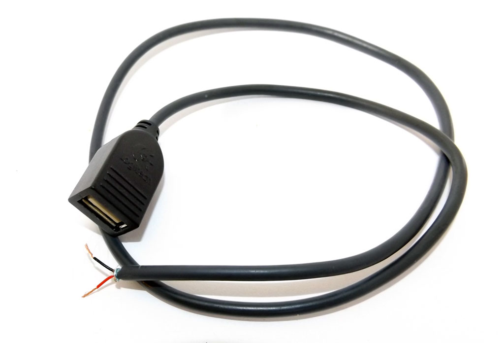
the cable to the hole with a couple small zip ties and shrunk the shrinking tube. VoilĂ , an USB power output. I've tried directly with a lot of devices (phones, e-readers etc) I had lying around - no problem. Even connecting an old 1.1 USB hub as a port mutiplier works, but I've the feeling that in this case the hub is limit the current output somehow.

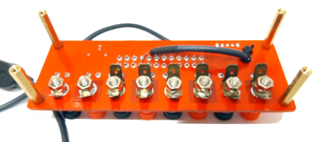
Here is the modified board from above, with the new binding posts:

Here it is from below. Note that I left the soldering clips on, they could be used for alligator clip cables, and that I added also some faston connectors I had around (only six because I had only six around, and for a long time as well...)

Another idea I had is to recycle the power cable from an old, broken wall-wart PSU to have a power output for my Arduinos. The barrel power plug on Arduinos accepts 5V-12V. I connected two fastons on the cable this way (check the connection with a multimeter, Arduino need a tip positive connection but in my case the tip was connected to the wire strand with a minus sign all along, even if the wall war was tip positive!):

And I connected to.. the -12V rail inverting + and -. The reason is that on my PSU the 12V is a bit higher, while the -12V is spot on. -12V has fewer amps, but sufficient for any Arduino test. Of course, one could use ring or clip on connectors instead of my old fastons.

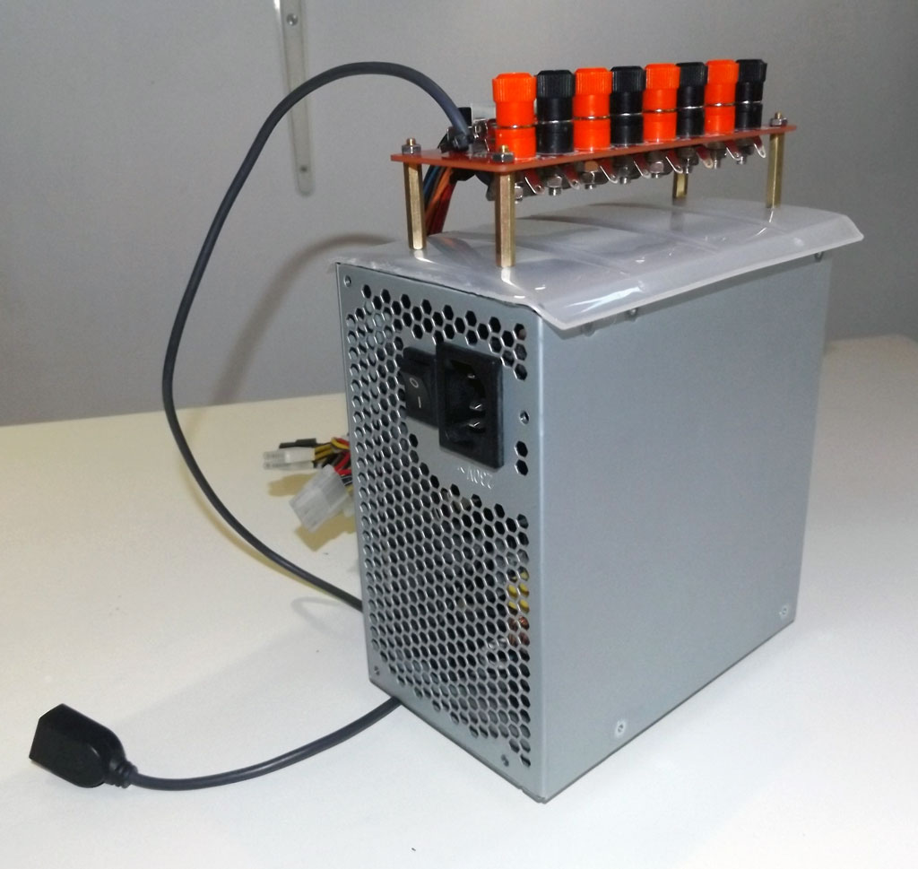
As a final touch, I looked in the kitchen. I found the cover of an old tupperware like box: it was more or less of the right size and was also conveniently convex. I sawed off the edges and drilled four holes to connect the brass posts. The fact that the cover is convex avoids the board standing on the M3 screws I used and allows for a better grip on the bench (or the ATX PSU) anyway.


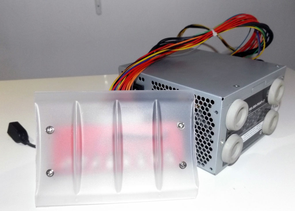
I also had some adhesive rubber feet from a long gone, 20 year old computer case. I put it on the back of the PSU to help it stand vertically. Here is the finished unit.

If you want to see the unit in action, I've shot a short video:


That's it. The next step would be to add a voltage regulator, something based on the LM317 (with low amperages) or LM350 (slightly more powerful). There are some ultra-cheap chinese kits, even with a voltmeter which could do the trick. We'll see...
Of course, if you want to get the board and modify it like I did, please make sure to know what you're doing and to take the necessary precautions when working with electrical devices and/or soldering equipment.


Saturday 26 August 2017

Controlling a ICStation relay board (ICSE013A ICSE012A ICSE014A) from .Net (and Arduino)

The other month, both for personal and professional interest, I began to explore the world of automating electrical devices connected to mains supply. That is, switching on and off electrical loads with relays. In order to start with something simple, I found an ultra cheap two relay board on ebay, compatible with both PCs, Arduinos and Raspberry PIs. It's probably the cheapest device of its kind available - I got it for 2.75 EUR shipped from China to Italy in about three weeks (!). It's called a ICSE013A board from http://www.icstation.com/

I don't know if the device is actually still produced, but it's part of a family of similar boards, along the ICSE012A (4 relays) and ICSE014A (8 relays). Here is the bare-bones board, it's shipped in bubble wrapped plastic bag with no instructions:


As you can see, it features two SPDT 5V chinese relays, a micro USB connector, and four pins on the left with places for an internal serial interface - see the back:


It's the 5V/GND/TX/RX - this is a 3.3V level serial interface for communincating with other microcontrollers like the Arduino - NOT a 12V RS-232. The microUSB connector supports a USB-to-serial interface via the bigger "Prolific PL2303" SMD chip near the crystal (more on this soon). The other chip is presumably the microcontroller.
As you can see from the photos, the construction quality is really poor, look a those opaque soldering spots - sheeesh. Here is the board on some old distancers: it's not that I did not have a matching chrome M3 screw, it's just that only the black screw could fit on that particular corner!


Now, regarding the 'Prolific' USB-Serial chip. I was aware of the problem before ordering the board, but it's really a counterfeit Prolific chip. These fake chips were very common in cheap USB-RS232 cables, until Prolific released drivers that recognized them and disabled the device in Windows, yellow icon and a Code 10 error. Counterfeit or not, these chips do work, but the lack of drivers, as well as  the fastidious habit of the recent iteration of  M$ operation systems to use only the most recent drivers from Windows Update render often these devices unusable. With other OSes like Linux there is no problem since the drivers have not this 'feature': it is however always possible to force an older still compatible driver with no particular issues. On Windows 7 64 bit I use the barebones zipped driver you can find here with an explanation. There is also this little program which could work better on Windows 8.x and 10 (but try the zipped driver first). In general google 'fake prolific chip fix' to get further informations and other drivers. With one of these fixes, the board will work in Windows. As far as I know, the other two boards with 4 and 8 relays all have fake chips.
From device manager it's seen in fact as Prolific USB-to-Serial Comm Port, and it's shown under the COM/LPT Tree. As with any other serial port, it's possible to assign a different COM port number from the properties dialog window.
Unlike boards with more relays this particular one has no need of additional power other than the standard USB 500mA - it's probably better to use a board USB socket anyway. There are also four miniature LEDs, one for each relay and two to signal RX/TX. Strangely, the first relay LED is noticeably brighter in my case.

Software and documentation must be downloaded from the manufacturer's site. Try here - it's the 4 relay board, but it's the same. What you get is a test program for Windows and two pages of documentation. There is a chinese version and an almost incomprehensible 'chinenglish' translated version. The theory of operation is actually pretty simple, even if to verify it I resorted to monitoring the serial traffic from/to the test program with a serial software monitor. To control this board, and the others, one must operate as following :

  • Set the serial parameters to 9600 bit/s, 8 bit data, no parity, 1 stop bit
  • The board  expects single byte commands and outputs single byte id packets.
  • When plugged in/switched on the board expecs an hex 50 command. When sent this command before operations the board will respond with a single byte id code. For the ICSE013A 2 relay board its hex AD. AB for the 4 relay model and AC for the 8 relay model
  • After this one must send an hex 51 command to start switching relays on and off. After this command, sending a request id hex 50 will no more result in the board sending back its id until it's switched off and then on. 
  • So to initialize the board first send hex 50, handle the id code if needed, then send hex 51.
  • To switch relays on and off and on one must always compute a single byte command representing the status of the individual relays. The first relay is represented by the lowest order bit in the command byte, the second in the second lowest order bit, and so on for the other relays of the other boards. Of course a 'switched on' relay with the NO contact closed it's represented by a 1 bit, the reverse by a 0 bit.
  • For the 2 relay board, the command to set both relays off it's 0, binary 00000000. To switch the second relay on, it's decimal 2, binary 00000010. To switch on both relays, it's dec 3, binary 00000011, to switch on the first relay, dec 1, binary 00000001.
  • It must be noted that the command always switches on AND OFF relays according to its data. For example if both relays are on and I send a 00000001 command only the first relay will be kept on, since the second-lowest order bit it's 0, that is, switch off relay 2!
  • In other words, the board does not keep the state of its relays in its protocol, this is always the programmer's responsibility. There are NO commands to retrieve the relays status.
  • It's also important to set a starting state for the relays beginning operations, since the hex 51/50 commands act strangely in this respect (a 51 command seem to switch a relay off when issued for the second time, e.g.)
  • Bits for relay not physically present on the board, for example trying to set the 8th relay on the 2 relay board, are simply ignored.
For .NET/C# I've written a simple test program in VS2010 which runs on every version of Windows, from XP with .Net 4.0. Choose port, request id, send the init command, play with relays. There is also a continuous test mode which can run very fast, use at your own risk. You have to init the board as described above to make it work: choose the right COM port before beginning. The program and its source is on github, here. Please note that I used only the .Net serial support methods handling   byte data directly. Do not use methods involving strings, since the encoding and UTF support in .Net will always produce confusing results. The PORT_DELAY constant can be probably safely reduced.

Now, after just a few hours of testing, the board started behaving erratically. Sometimes it shows 'Unknown USB device' when plugged in (on several hosts) - sometimes it works but only for a litte while. I suspect that one of the SMD capacitors or resistors on the board has experienced some infancy problem, or the Prolific chip is not only a fake, but also a trickster :-). The other relatively bigger M7 black component is a diode and it tests ok with my multimeter. Still good for the price and its purpose in my case, playing around. Using the other serial interface on the other hand does not show any problem: I soldered a 4 pin strip on the holes and I used an Arduino Uno as a testbed. The wiring is 5V board to 5V Arduino, GND board to GND Arduino, RX board to TX Arduino and TX board to RX arduino (TX/RX arduino are the first two digital pins). I wrote a simple sketch to loop the four possible relay states after initialising the board. It's  on github too, here. It will work with other Arduino models and other Arduino serial with minimal modifications. RX/TX must always be connected 'crossing', and always remember that it's NOT an RS-232 level interface. The 5V lead will power the board, no need to connect to USB.

What can I say? For 2.75 EUR, it's OK; if it dies completely I'll scrounge the relays and the terminal blocks..

Saturday 22 July 2017